|
Stafford Fusion Lab
|
|
|
Researching the future
|
|
|
|
|
|
Vacuum system
To achieve fusion a good vacuum is required, the following chart shows a range of tokamaks that have been used successfully and the vacuum they have achieved:
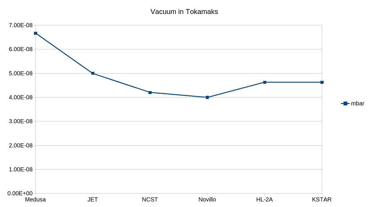
Medusa - (Garstka, 1997), Jet - (Pearce et al., 2001), NCST - (Huang et al., 2023), Novillo - (Valencia-Alvarado et al., 1983), HL-2A - (Zeng et al., 2005), KSTAR - (Kim et al., 2009).
As the pump down pressure achieved in the Medusa system (Garstka, 1997) of 2.7E-7 mbar (improved to 6.7E-8 mbar using a titanium getter) is in the molecular flow region (Santeler, 1966), the limit on the pumped flow rate will be the cross sectional area of the connection to the vacuum chamber which in the case of the Medusa vacuum chamber consisted of two 5.1cm diameter holes giving an area of 13.005Π cm2 and for a vacuum chamber using an ISO63 connection with an internal diameter of 6.3cm the area is 9.9225Π cm2 which is only 23.7% less, so a similar vacuum should be achievable using a turbomolecular pump with an ISO63 inlet port.
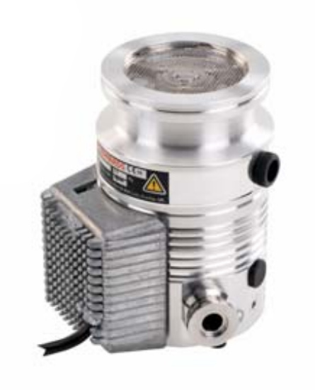
Based upon this the target vacuum will be around 5E-8 mbar, which should be achievable using viton seals (Ideal Vacuum, 2023) and an Edwards EXT75DX turbomolecular vacuum pump (Edwards Ltd, 2007)) similar to the one shown below (left).
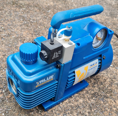
The turbomolecular vacuum pump requires a rotary backing pump on the outlet and the V-i120SV (Value, 2009) pump meets the required criteria and is shown below (right):
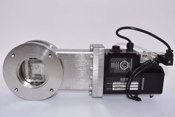
The turbomolecular vacuum pump is connected to the vacuum chamber via an LGV-2500V-P 307003 MDC high vacuum pneumatic gate valve (MDC Precision, 2019) as shown below (left).
The electrical connector required to connect the gate valve to the control system is a Switchcraft connector (part number 3282-7SG-318) available from Mouser Electronics.
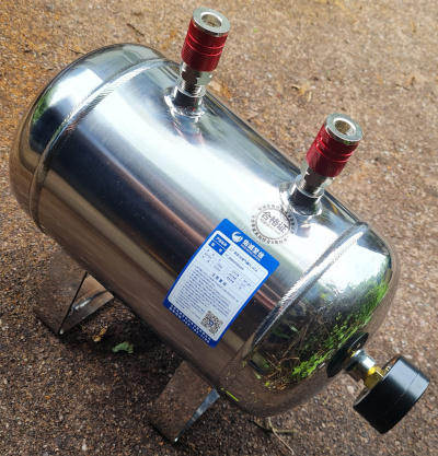
As pneumatic gate valves requires a compressed air source and the humphrey 410 solenoid valves (Humphrey, 2021) can be used with a maximum pressure of 8.5 bar, a 5 litre pressure vessel capable of withstanding 12.5 bar with a 10 bar pressure relief valve and a pressure gauge is used as an air reservoir as shown below (right)
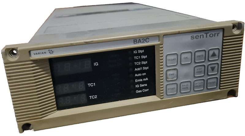
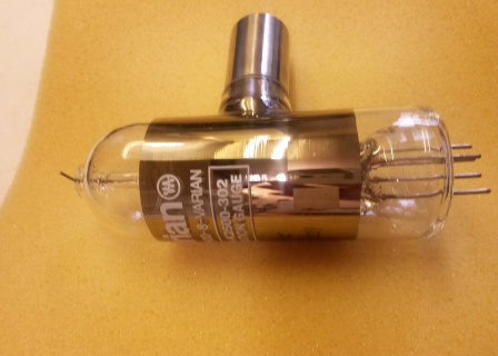
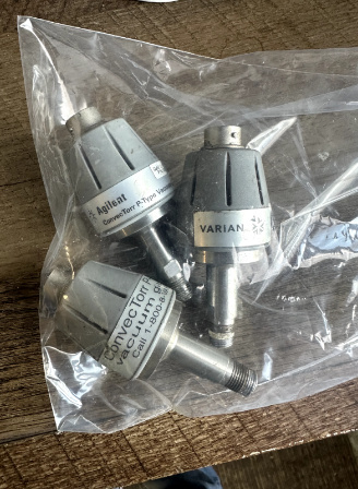
To measure the vacuum pressure a SenTorr BA2C Vacuum gauge (Varian, 1995) will be used with a 0564-k2500-302 Varian hot cathode ion gauge (Agilent, 2002) which uses a 5 Way Mate N lock connector cable (Varian, 2006) and two L9090301 Varian ConvecTorr gauges (Agilent, 2021) with this pinout (Varian, 2004) and 9 pin D-Sub cable (Varian, 2006) as shown below:
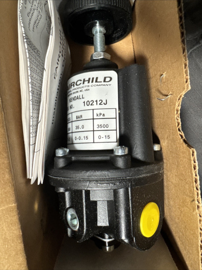
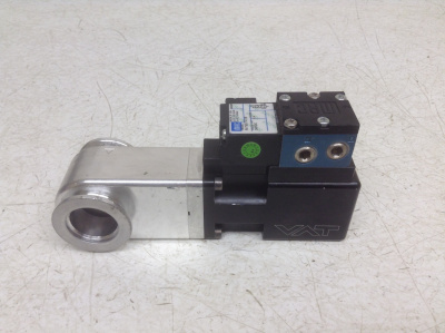
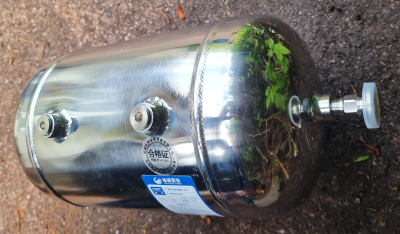
The deuterium used will be from a lecture size bottle of gas and once a small volume of gas has been released from the bottle into a short section of pipe by opening the bottle valve, the bottle valve will then be closed and a needle valve at one end of the pipe opened to allow the gas to flow into a 5 litre storage vessel (shown below right), the needle valve will then be closed and the lecture bottle removed. From the 5 litre storage vessel the gas will be reduced to 1 mbar using a Fairchild Model 10 (10212J) regulator (Fairchild, 2007) as shown below (left), before being fed through 2 meters of 2mm internal diameter tube to a VAT 01228-KA44-0001/0569 gate valve (VAT Vakuumventile AG, 2012) (shown below middle).
An RS232 output connection is an optional extra on the SenTorr BA2C but was not installed on the equipment available so an RS232 interface board has been made based upon the L6439-301 PCB (Varian, 1997), the new circuit (Stafford Fusion Lab, 2026a) has been produced on veroboard (Stafford Fusion Lab, 2026b) and confirmed as fully functional using the communications protocols shown in the manual (Agilent, 2004), so when filling the vacuum chamber with deuterium the gate valve supplying the restricted flow of deuterium can be closed when a pre-defined pressure (around 0.24 mtorr) has been reached allowing for accurate repeatable configuration of the tokamak.
Ideally grade N5.0 deuterium would be used (99.999% purity), unfortunately the only deuterium that could be obtained was N2.8 (99.8% purity), however the isotope analysis showed that the major impurity was Hydrogen-Deuterium molecules (at 2009ppm), with a low level of H2 molecules (at 1ppm) and N2 molecules (at 0.6ppm) with everything else being below measurable limits:
O2 (less than 0.2ppm),
CO (less than 0.2ppm),
CO2 (less than 0.2ppm),
Water content (less than 0.5ppm),
total hydrocarbon content (less than 0.2ppm).
It was decided that this level of purity would still be acceptable because it is the heavier molecules which have a disproportionate effect on cooling of the plasma (Stacey, 2010) that need to be as few as possible and the isotope analysis showed that if the hydrogen-deuterium molecules (which will have a limited amount of plasma cooling) were not taken into account the purity would be better than the equivalent of N5.0 (10ppm of impurities).
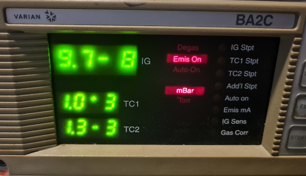
The first test of the vacuum system has resulted in vacuum of 6.6E-5 mbar after running the system for 31 minutes (the target vacuum is 2.7E-7 mbar before using a titanium getter), the setup is shown below:
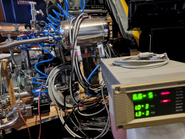
In the photo the sensor TC1 shows atmospheric pressure (1.0E3 mbar) and TC2 displays the minimum value that the sentorr gauge will read which is 1.3E-3 mbar (1.0E-3 torr).
The deuterium feed part of the system has been separated from the vacuum system using DN25 and DN16 blank flanges.
The total running time, excluding the time to get back to previously achieved vacuum pressure is shown below:
Atmospheric pressure --(31 minutes)-->6.6E-5mbar
6.6E-5mbar--(26 minutes)-->4.5E-5mbar
4.5E-5mbar--(21 minutes)-->1.3E-5mbar
1.3E-5mbar--(52 minutes)-->9.0E-6mbar
9.0E-6mbar--(171 minutes)-->2.3E-6mbar
2.3E-6mbar--(80 minutes)-->1.7E-6mbar
1.7E-6mbar--(432 minutes)-->1.0E-6mbar
1.0E-6mbar--(420 minutes)-->9.3E-7mbar
9.3E-7mbar--(420 minutes)-->7.0E-7mbar
7.0E-7mbar--(150 minutes)-->7.0E-7mbar
7.0E-7mbar--(390 minutes)-->6.5E-7mbar
6.5E-7mbar--(240 minutes)-->6.0E-7mbar
This gives a running total of the time to improve pressure readings of 40 hours 33 minutes (the last run was 14 hours 11 minutes long).
After removing the turbomolecular pump to install the water cooling some tests were carried out and it was found that TC2 was leaking, as the ConvecTorr gauge has a 1/8 inch NPT thread which is intended to be single use it was not possible to get a good vacuum seal. Therefore the ConvecTorr gauge was removed and the connection blanked off, it will be reinstalled later when the connection between the gauge and the DN16 ISO-KF connector has been sealed with Loctite EA 1C epoxy adhesive (Loctite EA 1C epoxy adhesive is sold by numerous vacuum component supply companies as a vacuum sealing adhesive).
The system was then run for 12.5 hours to get to 7.0E-7 mbar, 16 hours to 6.9E-7 mbar, 13 hours to 7.0E-7 mbar and 9 hours to 7.9E-7 mbar (with the system shutdown between each run).
At this point the system was then run for:
25.0 hours to get to 6.2E-7 mbar (average over 25.0h 8.7E-7 mbar), then left on for another
24.5 hours to get to 5.0E-7 mbar (average over 24.5h 5.6E-7 mbar), then left on for another
22.0 hours to get to 4.7E-7 mbar (average over 22.0h 5.1E-7 mbar), then left on for another
26.0 hours to get to 4.7E-7 mbar (average over 26.0h 5.2E-7 mbar), then left on for another
23.5 hours to get to 4.5E-7 mbar (average over 23.5h 4.9E-7 mbar), then left on for another
24.5 hours to get to 4.3E-7 mbar (average over 24.5h 4.8E-7 mbar), then after
48 hour partial bakeout to get to 3.5E-7 mbar.
The system was then shutdown, then powered back up with heat applied from the start, after 4 additional days partial bakeout and 2 days without heating 3.5E-7 mbar was again reached.
7 additional days partial bakout , (2 sections, including one at 70 degrees centegrade) to get to 3.5E-7 mbar, at this point it is believe the majority of contamination had been removed from the ISO63 gate valve.
12 additional days partial bakout, (6 sections, including one at 70 degrees centegrade) to get to 1.3E-6 mbar (during heating) giving 1.1E-7 mbar after cooling.
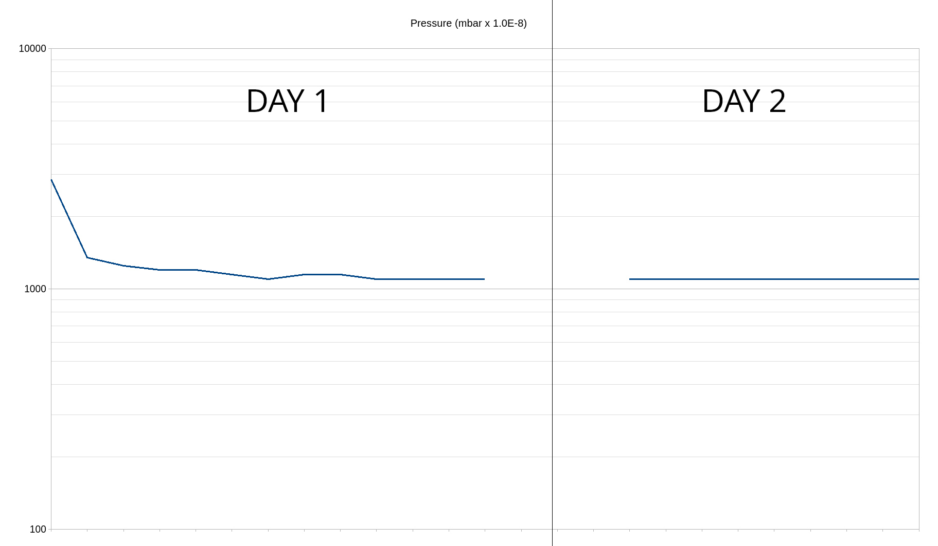
A 20cm ISO63 section was added along with heated wire, in addition 3 sections of DN25 tube were added (20cm DN25 bellows, 90 degree DN25 elbow and 20cm DN25 straight) and along with the two existing DN25 sections these were split into 2 more heated sections, the DN25 sections were terminated with a DN25 gate valve. The system was re-started and the pressure levelled off at 1.1E-5 mbar.
The DN25 gate valve was removed and once the system dropped to 1.3E-6 mbar heat was applied and maintained for 5 days and once 1.4E-6 mbar was reached during bakeout the heat was removed and the pressure dropped to 9.7E-8 mbar.
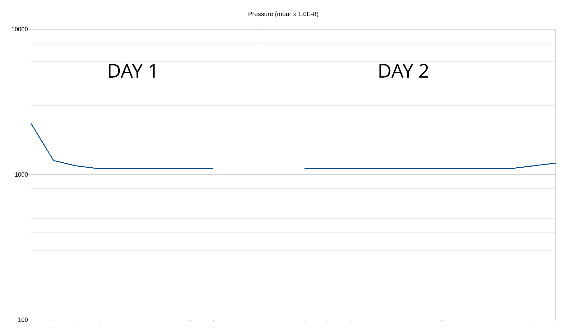
The DN25 vacuum flanges on the gate valve were filed and sanded with increasingly fine grades of sandpaper to achieve a good surface finish and the DN25 gate valve was added back into the system. The system soon levelled off at 1.1E-5 and remained at that pressure overnight, even after heat was applied there was only a slight increase in pressure suggesting that the cause was a leak rather than surface contamination. The DN25 gate valve was taken apart and thoroughly cleaned using methanol on cotton buds and even though the methanol would contaminate the FKM seals the existing contamination was a great deal worse. After cleaning of the DN25 gate valve it was added back into the system and after 22 minutes the pressure had dropped to 1.8E-6 showing that the leak had been resolved.
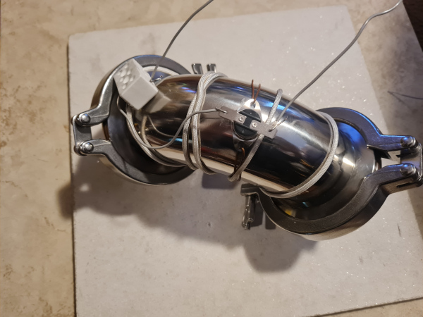
It has been decided that to speed up the desorption rate (Edwards Vacuum, 2024) the vacuum system will need to be heated, however the maximum inlet-flange temperature of the turbomolecular vacuum pump when cooled with water is 70 degrees centigrade (Edwards Ltd, 2007)), so up to but not including the vacuum adapter conected to the turbomolecular vacuum pump the system will be heated to around 100 degrees centegrade using nichrome wire in heat resistant fibreglass sleeve wrapped around each section with a thermostat (110 degrees Centegrade open/90 degrees Centegrade reset - close) controlling each of those sections. The section adjacent to the turbomolecular pump will be heated to a maximum of 70 degrees centegrade.
A test has been carried out using 1.07 metres of 1.2mm diameter 0.96 ohms/metre nichrome wire in a heat resistant fibreglass sleeve wrapped around a section of the vacuum system (see photo below) with a 110 degrees centegrade open/90 degrees centegrade reset - close thermostat. Initially 3V was applied and it was found that the heating wasn't sufficient, the applied voltage was increased 1V at a time until 9V was reached, at which point a current flow of approximately 8A (72W) was found to switch the thermostat between an on and off state every two minutes (the length of wire used for heating is slightly shorter than 1.07 metres due to some of the wire being in the ceramic connector block resulting in a slightly higher current than one would expect). It was later found that even though the fibreglass sleeve provided adequate insulation when the nichrome wire was wrapped around the tubes, when it was wrapped around any edges even if they were rounded a short circuit would occur, applying some thin insulating tape at those points of contact provided a suitable level of insulation.
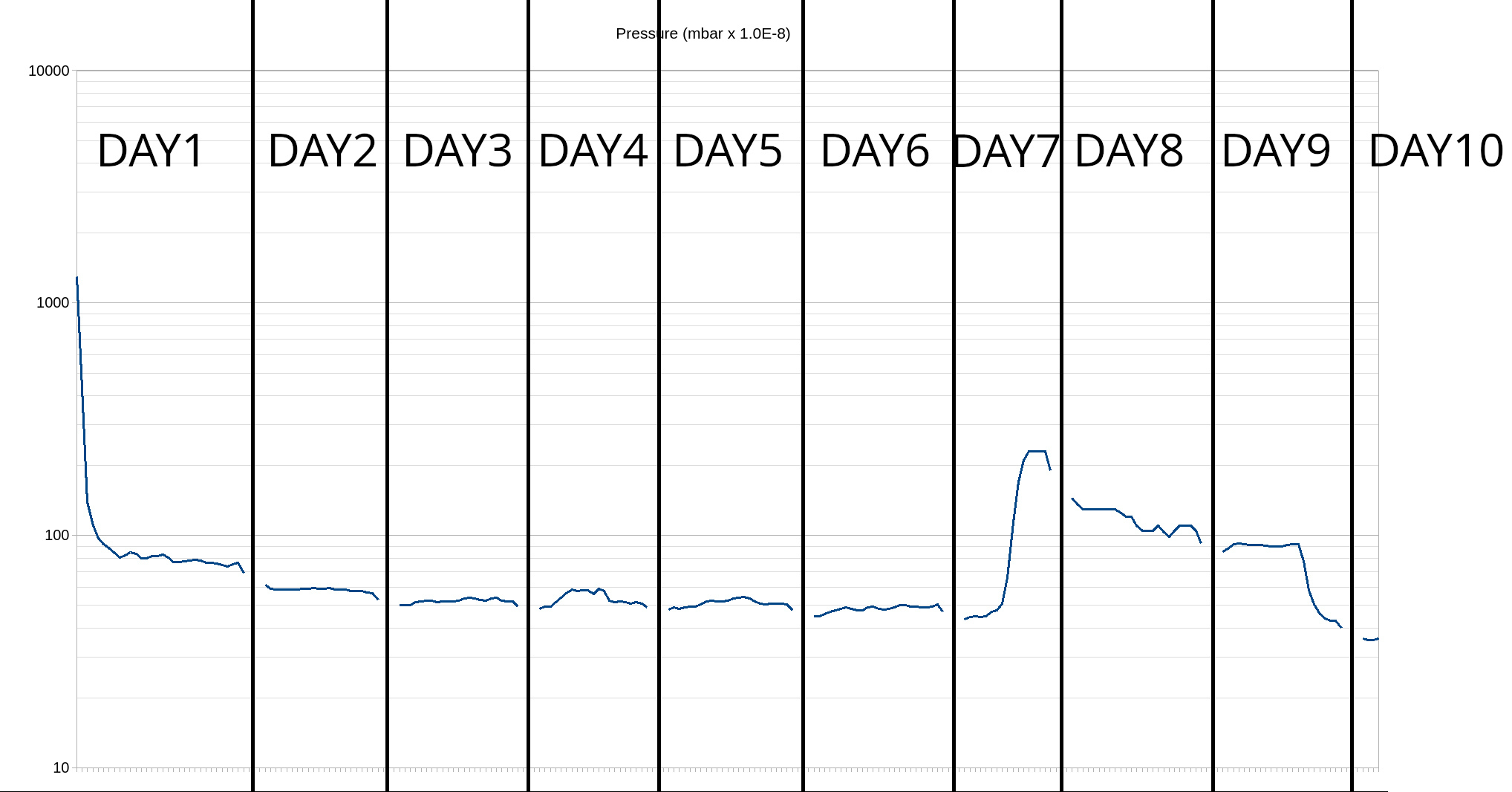
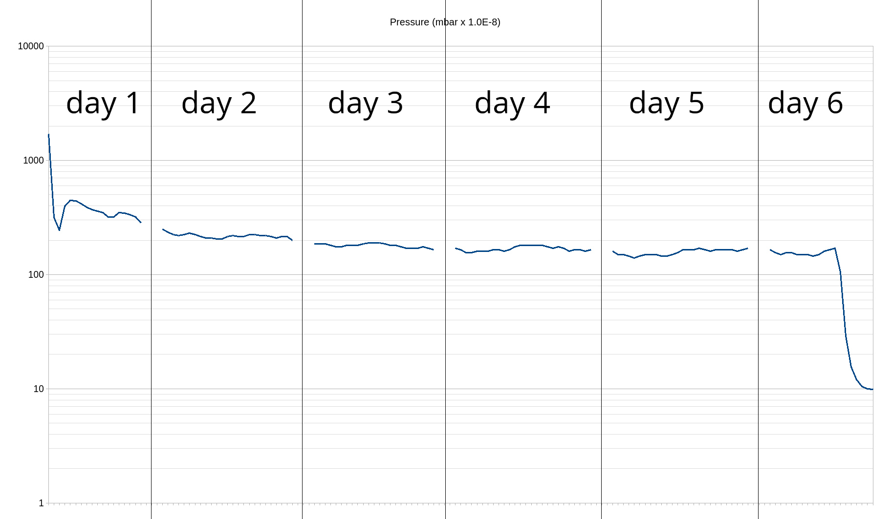
An initial test has been carried out heating one section of the system, it was carried out on the ISO63 gate valve as that was believed to be the most contaminated and since cleaning of the main o-ring and any other viton components isn't advisable (Danielson, 2006) the only safe method of removing any surface contaminants is through heat and vacuum. The temperature of the section did not reach the intended 100 degrees centigrade due to heat being conducted through to the adjacent sections (in the final system the adjacent sections will also be heated), the temperature that was reached was believed to be approximately 70 degrees centegrade. The section was heated for 48 hours and during the first few hours there was a significant chemical odor due to the surface contamination being desorpted. The graph below shows the system pressure gradually reducing over the 6.5 days and the heat then being applied to the gate valve section for 48 hours, after which the pressure reduced to a new minimum system pressure of 3.5E-7 mbar. As only one section was heated some of what was desorped will have condensed on the cooler sections resulting in a reduction in the overall improvement. It is believed that some contamination is still present on the gate valve which will hopefully be desorped when the full system is subject to a bake out at the full temperature.
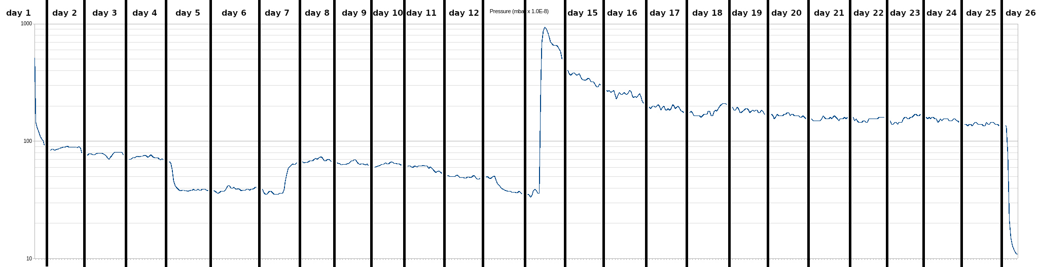
The system was then restarted with heat applied from the start, on day 5 the heat was removed and after another 2 days the pressure levelled out at around 3.5E-7 mbar and the heat was re-applied. On day 13 the heat was removed and by the next day the pressure had again dropped to 3.5E-7, at which point an additional four sections heated to 100 degrees were added, on day 18 some insulation was wrapped around the three unheated sections and the heat spread through the first two of them leaving the end section at room temperature. On day 26 the pressure had dropped to 1.3E-6 mbar whilst heated, the heat was removed and the pressure dropped to 1.1E-7 mbar.
The graph below shows the system running with the addition of ISO63 bellows, additional DN25 sections and a DN25 gate valve - the gate valve caused the pressure to remain at 1.1E-5 mbar
The graph below shows the same system with the DN25 gate valve removed and achieved a final pressure of 9.7E-8 mbar:
The graph below shows the second test of the system with the DN25 gate valve, which again caused the pressure to remain at 1.1E-5 mbar, the right hand end of the graph shows a slight increase in pressure when the entire system was heated, the increase in pressure was comparable with the change that previously occured without the gate valve present which suggests that the source of the problem is most likely some sort of leak as a large increase would have been expected if the cause had been outgassing of surface contaminants.
After cleaning of the DN25 gate valve it was added back into the system and after 22 minutes the pressure had dropped to 1.8E-6 mbar showing that the leak had been resolved.
After checking the settings on the BA2C vacuum gauge it has been necessary to change from the default settings to an emission current of 0.1mA and to an ion sensitivity to 8A/torr as that is what is required for the model 564 Varian broad range Bayard-Alpert gauge, this has resulted in the pressure now reading approximately 20% higher pressure than previously, however since gauge to gauge accuracy can differ by 25% for the same make and model of BA gauge this difference will not have a significant effect on the accuracy of the pressures recorded. (Stanford Research Systems, 2005)
Once the vacuum system is attached to the vacuum chamber the final pressure achievable will likely be higher, so it is important to achieve as low a pressure as possible with the vacuum system not connected to the vacuum chamber.
The Medusa system (Garstka, 1997) used a similar vacuum system to achieved a pump down vacuum pressure of 2.7E-7 mbar and then used a titanium getter (Clausing, 1961) to achieve the final pressure of 6.7E-8 mbar, so as long as a pressure of less than 2.7E-7 mbar is achieved through mechanical pumping it is expected that the target pressure of around 5E-8 mbar should also be achievable.
References
Agilent (2002). 564 Ionization Gauge Tube Instruction Manual. Document No. 699905564.
Agilent (2004). RS-232 and RS-485 Options for the senTorr Guage Controller. Document No. 699908170.
Agilent (2021). ConvecTorr Gauge Tube Data Sheet.
Clausing, R. E. (1961). A Large-Scale Getter Pumping Experiment Using Vapor Deposited Titanium Films. Oak Ridge National Laboratory, U.S. Atomic Energy Commission
Danielson, P. (2006). The Use and Misuse of O-Rings. A Journal of Practical and Useful Vacuum Technology.
Edwards Ltd (2007). EXT Compoind Turbomolecular Pumps EXT75DX, EXT75iDX, EXT255DX AND EXT255iDX Instruction Manual.
Edwards Vacuum (2024). Application Note: Outgassing.
Fairchild (2007). Fairchild Model 10 Pneumatic Precision Regulator Installation, Operation and Maintenance Instructions.
Garstka, G (1997). Startup and Stability of a small Spherical Tokamak. Dissertation University of Wisconsin-Madison. UMI Number 9803422.
Huang, F. H. et al. (2023). Design of vacuum system for NCST spherical tokamak. AIP Advances 13, 085313 (2023); doi: 10.1063/5.0160942
Humphrey. (2021). Humphrey 310/410 Series Inline Solenoid Valves
Ideal Vacuum (2023). Common Vacuum Fittings and Connections Selection & Assembly Guide
Kim, S. T. et al. (2009). Baking results of KSTAR vacuum vessel. Transactions of the Korean Nuclear Society Spring Meeting, Jeju, Korea, May 22, 2009
MDC Precision. (2019). MDC Precision Catalog - Imperial Section 2A
Pearce, R. et al. (2001). Vacuum Pumping Developments on the JET Tokamak. EFDA-JET-CP(00)01/07.
Santeler, J.S. et al. (1966). Vacuum Technology and Space Simulation. NASA SP-105, Washington, D.C.
Stacey, W.M. (2010). Fusion: An Introduction to the Physics and Technology of Magnetic Confinement Fusion (2nd Ed.).Wiley-Vch. Weinheim.
Stafford Fusion Lab (2026a). Circuit designed by Stafford Fusion Lab based upon Varian L64390-301
Stafford Fusion Lab (2026b). Veroboard designed by Stafford Fusion Lab based upon Varian L64390-301
Stanford Research Systems (2005). Select the Best Bayard-Alpert Ionization Gauge for Your Application.
Valencia-Alvarado, R. (1983). Vacuum System of the Tokamak Novillo. Instituto Nacional de Investigaciones Nucleares, Laboratorio de Fisica de Palmas, Mexico.
Value (2009). Value iPump Vacuum Pump Operation manual
Varian (1995). senTorr Gauge Controller - Instruction manual
Varian (1997). Based upon photos of L64390-301 PCB.
Varian (2004). Wiring Diagram - All models
Varian (2006). Instructions for Varian Gauge Cable Connector Kits. Document No. 699908080.
VAT Vakuumventile AG (2012). VAT Installation, Operating & Maintenance Instructions Series 012, DN 16-50 (I.D. 5/8" - 2") Mini gate valve with pneumatic actuator double acting
Xeng, C. et al. (2005). Vacuum System HL-2A Tokamak Cao Zeng et al 2005, Plasma Sci. Technol. 7 2632. doi: 10.1088/1009-0630/7/1/007
Any enquiries should be directed to: admin @ staffordfusionlab.co.uk

